Publicerad i #TRENCHLESS INTERNATIONAL | FALL 2016 | – 20 oktober, 2016
3R2014: STRUCTURAL DESIGN FOR NON-CIRCULAR LININGS UNDER GROUNDWATER PRESSURE
The 3R2014 design guidelines present a secure design method for the resistance of non-circular linings to the groundwater pressure. The following technical paper will be presented in more detail at No-Dig Beijing on 10-12 October, including a comparison with the recent German code DWA A 143-2 and WRC-SRM type 2 method.
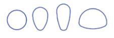
With the rapid development around the world of plastic flexible liners such as cured-in-place pipe (CIPP), prefabricated panels, and spirally wound profiles, there was an urgent need for a specific, comprehensive and safe design method for common non-circular cross sections (ovoid, arch shaped, oval, rectangular pipes) which national and international design methods had not covered. All national methods give importance to the groundwater pressure but only cover elliptical and special shapes; however, care should be exercised when using these methods for other geometry, especially egg-shaped sewer with flat sides. The new French recommendation for the design of liners, 3R2014, was published at the end of 2014 by the French Scientific and Technical Association for Water and the Environment (ASTEE). The design offers a significant contribution for the resistance of linings to groundwater, with an analytical design method applicable to challenging pipe shapes and is ready for computational tools.
DESIGNING FOR GROUNDWATER PRESSURE
The groundwater is the only action that acts directly on the lining. The other actions (earth pressure, traffic, etc.) act via the host structure and suppose further deformations or material degradation. If there is no existing groundwater, 3R2014 assumes a minimal water column of 1.5 m above the invert or 0.5 m above the top (both at the highest).
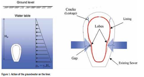
The lining shape has a great importance for the resistance to the external hydrostatic pressure especially the radius of the sides (for egg-shape) or the radius of the invert (for horseshoe shape). The initial annular gap between the lining and the host, created due to the shrinkage of the resin for CIPP, may also have a big influence on the resistance to buckling. When a lining is subjected to external pressure, circumferential compression develops and the lining’s perimeter shortens. Then a gap opens between the lining and the host and a lobe develops at the location of maximum radius of curvature where the circumferential compression is at its highest. Pressure in the lobe blows the rest of the lining into a tight fit against the host pipe.
THE GROUNDWATER IS THE ONLY ACTION THAT ACTS DIRECTLY ON THE LINING. THE OTHER ACTIONS (EARTH PRESSURE, TRAFFIC, ETC.) ACT VIA THE HOST STRUCTURE AND SUPPOSE FURTHER DEFORMATIONS OR MATERIAL DEGRADATION.
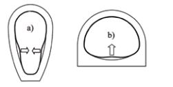
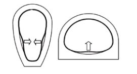
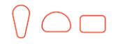
In the case of an egg-shaped lining, two lobes can develop at each side. This configuration is referred as ‘two lobes mode’. In the case of a horseshoe-shaped lining, one lobe can develop at the invert where the radius and the water pressure is at its highest. This configuration is referred as ‘single-lobe mode’
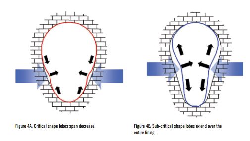
When the pressure grows, two opposite behaviours for the lobe’s development can be observed according to the shape:
• If the curvature and the extension angle of the arc, where the lobe develops are sufficient, the deflection at the center of the lobe increases but the angular span of the lobe decreases to a critical value αcr where inversion of the lobe occurs by buckling. Otherwise, for instance in the case of an oval shape or an egg shape with straight sides, the lobe may extend continuously over the entire lining without buckling instability. The first behavior is named ‘critical’ and the second ‘sub-critical’.
• Deflections of sub-critical linings under external pressure are much larger than those of critical linings .
• The key parameter for critical shape is then the buckling pressure while it is the deflection for sub-critical shape. Circular shapes, egg-shapes and horseshoe shapes with curved sides are critical. Egg-shapes with straight sides, horseshoe shapes with a flat bottom, or rectangular shapes are sub-critical. The 3R2014 design method offers two different analytical approaches for non-circular shapes with curved sides (critical shape) and non-circular shapes with straight sides (sub-critical shape). If the radius of curvature of the sides is not known, it should be assumed that the sides are straight and the method for sub-critical lining should be used (that can be very conservative). If the radius of the sides is large, it is possible to use both the two methods and then to choose the most favorable result.
DESIGNING FOR NON-CIRCULAR SHAPES WITH CURVED SIDES
The calculation method is based on a closed-form analytical solution established by Dr Olivier Thepot which extends Glock’s analysis to non-circular lining. The shape must be convex, comprising a succession or arcs tangent at their points of contact. The buckling pressure is given by the following formula:
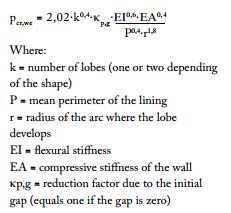
Where:
k = number of lobes (one or two depending of the shape)
P = mean perimeter of the lining r = radius of the arc where the lobe develops
EI = flexural stiffness
EA = compressive stiffness of the wall
κp,g = reduction factor due to the initial gap (equals one if the gap is zero)
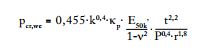
In case of plain wall and homogeneous material of thickness (‘t’), the formulas simplify as follows:
It is also easy to calculate the buckling pressure or a particular shape, for example the common 3 x 2 egg-shape:
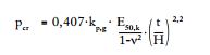
Where ‘H’ is the height of the shape (R=H, P=2.6433xH, k=2). For circular lining and plain wall the general formula simplifies to Glock’s solution:
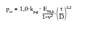
Where ‘D’ is the diameter. The bending moment, the axial force and the deflection at the center of the lobe are also calculated with analytical formulas. Comparisons with finite element analysis are excellent for the critical buckling pressure and fairly good for stress and deflection.
DESIGNING FOR NON-CIRCULAR SHAPES WITH STRAIGHT SIDES
The key parameter here is not the buckling pressure but the maximum deflection because non-circular shapes with straight sides are very deformable and they don’t exhibit buckling instability. The acceptable maximum deflection, which is a serviceability requirement, can be 2-3 per cent of the straight section or 10-20 mm for example. The calculation method is based on an analytical solution giving an explicit solution for the pressure (head of water) function of the maximum deflection. The steps of the design procedure are summarised in the figure below. In conclusion, the ASTEE 3R2014 recommendations offer a secure design method for the resistance of non-circular linings to the groundwater pressure. The method is entirely analytical and can be easily computed.
THE 3R2014 DESIGN METHOD OFFERS TWO DIFFERENT ANALYTICAL APPROACHES FOR NON-CIRCULAR SHAPES WITH CURVED SIDES AND NON-CIRCULAR SHAPES WITH STRAIGHT SIDES.

REFERENCES ASTEE (2014). Nouvelles recommendations pour le dimensionnement de la réhabilitation par chemisage et tubage des réseaux d’assainissement. TSM, N°10, October 2014. Moore I.D. (2009). Specialised design considerations for liners in gravity flow pipes. Trenchless International – January 2009. Thépot O. (2000). A new design method for non-circular sewer linings. Tunnelling and Underground Space Technology. Vol. 15, N°1, 25-41. Thépot O. (2001). Structural design of ovalshaped sewer linings. Thin-Walled Structures. Vol. 39, N°6, 499-518. Thépot O., Joussin J.M. (2007). The structural design of large non-circular GRP prefabricated liners. International No-Dig Rome.